Things in UML
A thing can be described as any real-world entity or an object. Things are divided into various categories in UML as follows,
- Structural things
- Behavioral things
- Grouping things
- Annotational things
Structural things
Structural things are all about the physical part of a system. It is the noun of a UML model, such as a class, object, interface, collaboration, use case, component, and a node.

Class :- A class is used to represent various objects. It is used to define the properties and operations of an object.
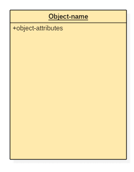
Object :- An object is an entity which is used to describe the behavior and functions of a system. The class and object have the same notations.
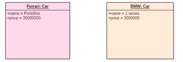
**Example of Object Diagram :-**The below UML object diagram contains two objects named Ferrari and BMW which belong to a class named as a Car. The objects are nothing but real-world entities that are the instances of a class.

Interface :- An interface is similar to a template without implementation details. A circle notation represents it. When a class implements an interface, its functionality is also implemented.
Behavioral things
They are the verbs of a UML model, such as interactions, activities and state machines. Behavioral things are used to represent the behavior of a system.
Interaction diagram :- Interaction diagrams are used to visualize the message flow between various components of a system.
Grouping things
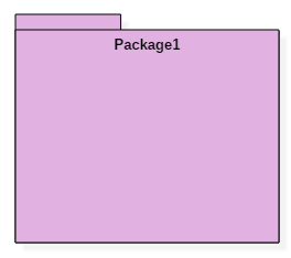
It is the package which is used to group semantically related modeling elements into a single cohesive unit.
Annotational things
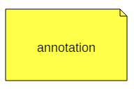
It is like a note, which may be written to the model to capture some vital information. It is similar to the yellow sticky note.
Relationships type in UML

The relationship allows you to show on a model how two or more things relate to each other.

Association relationship :- It is a set of links that connect elements of the UML model.It is denoted as a dotted line with arrowheads on both sides. Both the sides contain an element which describes the relationship.

Reflexive association :- Reflexive association states that a link or a connection can be present within the objects of the same class.

Directed association :- Directed association, the flow is directed. The association from one class to another class flows in a single direction only.


Dependency relationship :- It is one of the most important notations of UML. It defines the direction of a dependency from one object to another.


Generalization relationship :- It is also called as a parent-child relationship.This type of relationship is used to represent the inheritance concept.

Realization relationship :- Realization relationship is widely used while denoting interfaces.
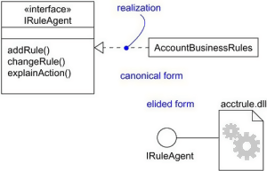
Realization can be represented in two ways:
- Using a canonical form
- Using an elided form

Composition :- Composite aggregation is described as a binary association decorated with a filled black diamond at the aggregate (whole) end.It is not a standard UML relationship, but it is still used in various applications.

Aggregation :- aggregation relationship, the dependent object remains in the scope of a relationship even when the source object is destroyed.An aggregation is a subtype of an association relationship in UML.
Abstract Classes

It is a class with an operation prototype, but not the implementation.In UML The only difference between a class and an abstract class is that the class name is strictly written in an italic font.
Lets see a complete UML class diagram example :-
ATMs system is very simple as customers need to press some buttons to receive cash. However, there are multiple security layers that any ATM system needs to pass. This helps to prevent fraud and provide cash or need details to banking customers.

UML Use Case Diagram
Use Case Diagram captures the system’s functionality and requirements by using actors and use cases. Use Cases model the services, tasks, function that a system needs to perform.

Use-case :- Use-cases are one of the core concepts of object-oriented modeling. They are used to represent high-level functionalities and how the user will handle the system.

Actor :- The actor is an entity that interacts with the system. A user is the best example of an actor.
Example of Usecase diagram
In the below use case diagram, there are two actors named student and a teacher. There are a total of five use cases that represent the specific functionality of a student management system. Each actor interacts with a particular use case.

UML State Machine Diagram

State machine:- It used to describe various states of a single component throughout the software development life cycle.
Their are 4 type of state in state machine :-
- Initial state :-The initial state symbol is used to indicate the beginning of a state machine diagram.
- Final state :- This symbol is used to indicate the end of a state machine diagram.
- Decision box :- It contains a condition. Depending upon the result of an evaluated guard condition, a new path is taken for program execution.
- Transition :- A transition is a change in one state into another state which is occurred because of some event.
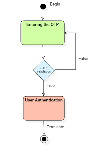
Example of State Machine Diagrams :- There are a total of two states, and the first state indicates that the OTP has to be entered first. After that, OTP is checked in the decision box, if it is correct, then only state transition will occur, and the user will be validated. If OTP is incorrect, then the transition will not take place, and it will again go back to the beginning state until the user enters the correct OTP.
UML Activity Diagram

Activity diagram :- activity diagram is used to represent various activities carried out by different components of a system.
- Initial states: The starting stage before an activity takes place is depicted as the initial state
- Final states: The state which the system reaches when a specific process ends is known as a Final State
- Decision box: It is a diamond shape box which represents a decision with alternate paths. It represents the flow of control.
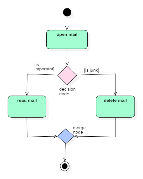
Example of Activity Diagram :-Following diagram represents activity for processing e-mails.
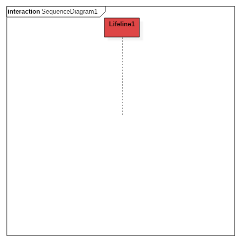
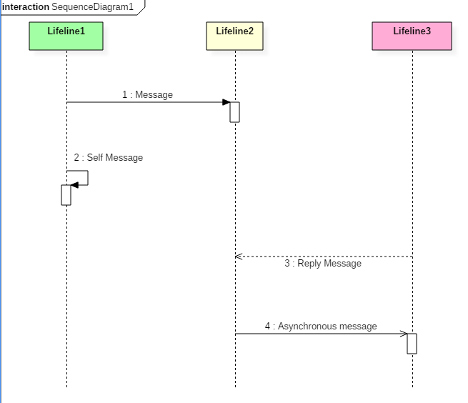
Sequence Diagram
The purpose of a sequence diagram in UML is to visualize the sequence of a message flow in the system.A sequence diagram is used to capture the behavior of any scenario.
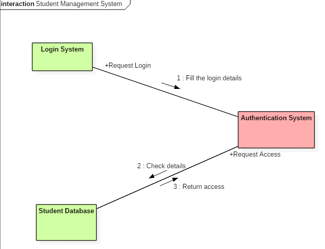
Collaboration diagram

Collaboration :- It is represented by a dotted ellipse with a name written inside it
Example of Collaboration diagram :-
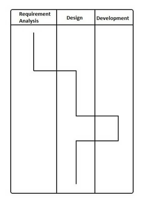
Timing diagram
A timing diagram specifies how the object changes its state by using a waveform or a graph. It is used to denote the transformation of an object from one form into another form.
Example of Timing diagram :-
UML Component Diagram
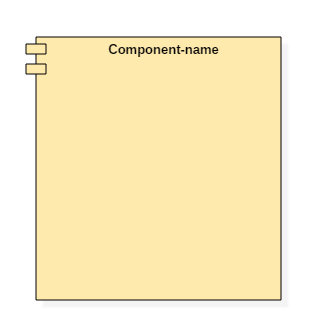
Component :- A component notation is used to represent a part of the system.

Node :- A node can be used to represent a network, server, routers, etc. Its notation is given below.
Structure of a component :-
A component is represented with classifier rectangle stereotypes as<< component >>.

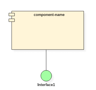
Port :- A port is an interaction point between a classifier and an external environment. It groups semantically cohesive set of provided and required interfaces.
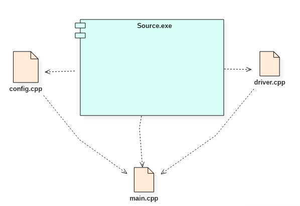
Example of Component diagram :-
Deployment Diagram
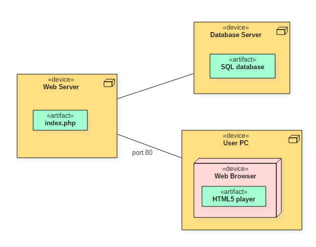
Deployment diagram :- A deployment diagram represents the physical view of a system.
A deployment diagram consists of the following notations:
- A node
- A component
- An artifact
- An interface

Example of a deployment diagram :- Following deployment diagram represents the working of HTML5 video player in the browser.